Qu'est-ce que la fréquence de croisement Fc, les pentes de croisement et pourquoi sont-elles importantes ?
Les croisements sont extrêmement important pour les systèmes de haut-parleurs et un gros raison pour laquelle nous sommes en mesure d'obtenir une qualité sonore que nous aimons.
D'un autre côté, des choses comme la fréquence de croisement (Fc), les pentes (db par octave, et comment tout cela fonctionne peuvent être un peu compliqués si vous ne comprenez pas comment tout cela fonctionne. J'aimerais vous aider !
Dans cet article, je vais vous expliquer :
- Qu'est-ce que la fréquence de croisement Fc et pourquoi est-ce important ?
- Qu'est-ce qu'une pente de croisement et la plus courante que vous rencontrerez
- Comment calculer la chute de croisement dB pour les fréquences incluant Fc
- Le rôle des inductances et des condensateurs (et la "réactance" pour Fc)
Fréquence de croisement Fc et pentes de croisement expliquées
Ce diagramme montre des exemples des 3 principaux types de filtres utilisés dans les croisements. Les pentes de croisement les plus courantes sont également indiquées. qui est la "pente" du filtre (l'efficacité avec laquelle ils bloquent les fréquences au-delà de la fréquence de croisement).
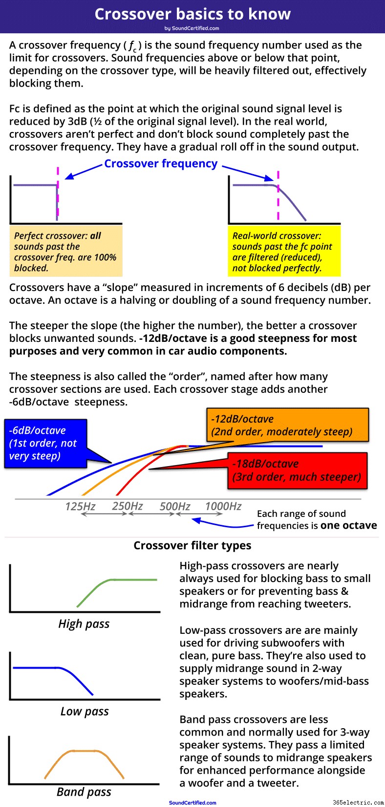
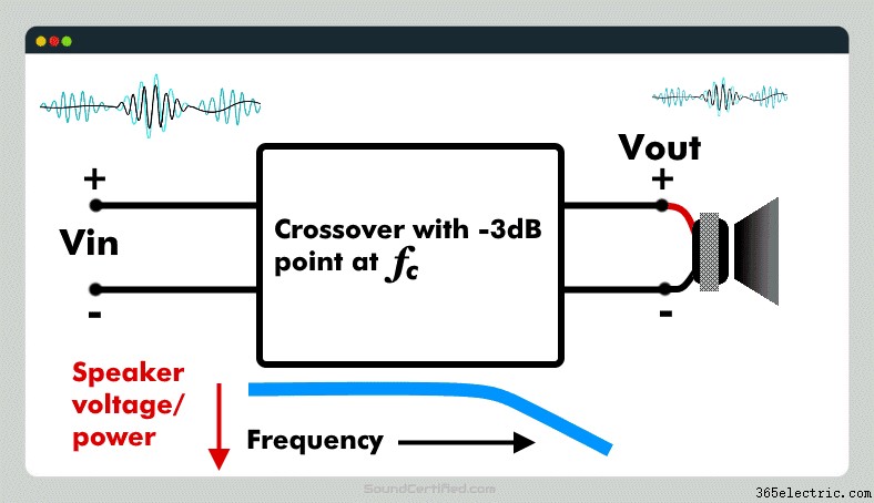
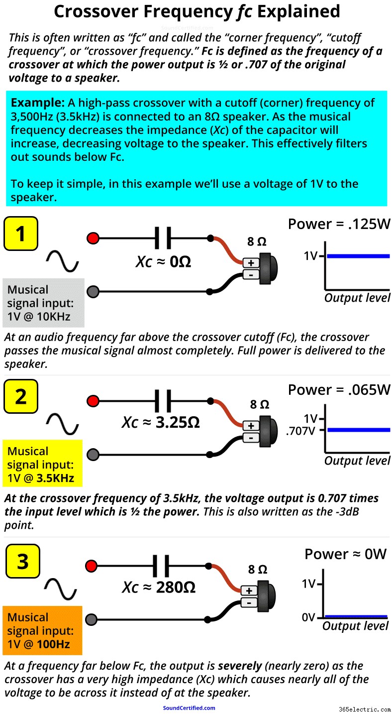
Une fréquence de croisement, communément écrite sous la forme Fc , est le point de fréquence audio en Hertz (Hz) auquel le crossover délivre une puissance de sortie de -3dB (1/2) au haut-parleur. Fc est le point de marquage après lequel les fréquences sonores seront fortement réduites pour les empêcher d'atteindre un haut-parleur.
Au-delà du point de fréquence de croisement (Fc), la puissance de sortie du croisement chutera de plus en plus, avec de moins en moins de puissance envoyée au haut-parleur. En l'occurrence, à Fc, la tension de sortie vers la charge (haut-parleur) est de 0,707 x la tension d'entrée, ce qui signifie que vous pouvez calculer la chute de décibels en fonction de la tension de sortie par rapport à la tension d'entrée.
Pourquoi les fréquences de croisement sont importantes
Lors de la conception des croisements d'enceintes, la fréquence de croisement (fc ) est utilisé comme une sorte de ligne qui marque où nous voulons commencer à bloquer les fréquences sonores envoyées à un haut-parleur. Il est généralement basé sur les spécifications fournies par un fabricant d'enceintes qui répertorie les fréquences sonores qu'une enceinte peut produire avec une bonne réponse sonore et sans distorsion.
Par exemple, les tweeters ne peuvent pas jouer les notes de basse de la musique et peuvent même être endommagés par celles-ci. Sachant cela, nous voudrions choisir une fréquence de croisement suffisamment élevée pour bloquer les notes de basse envoyées aux tweeters afin d'éviter toute distorsion ou dommage. (Généralement, les tweeters ont une fréquence de croisement dans les milliers de Hertz [écrit comme KiloHertz ou kHz pour faire court] comme 3,5 kHz, 5 kHz, et ainsi de suite - eh bien au-dessus de la gamme des sons graves et médium dans la musique).
Une fréquence de croisement est aussi parfois appelée la fréquence de coin ou fréquence de coupure puisque nous pensons en termes de la façon dont les sons sont "coupés" après ce point.
La fréquence de croisement Fc est très important pour la conception de croisement
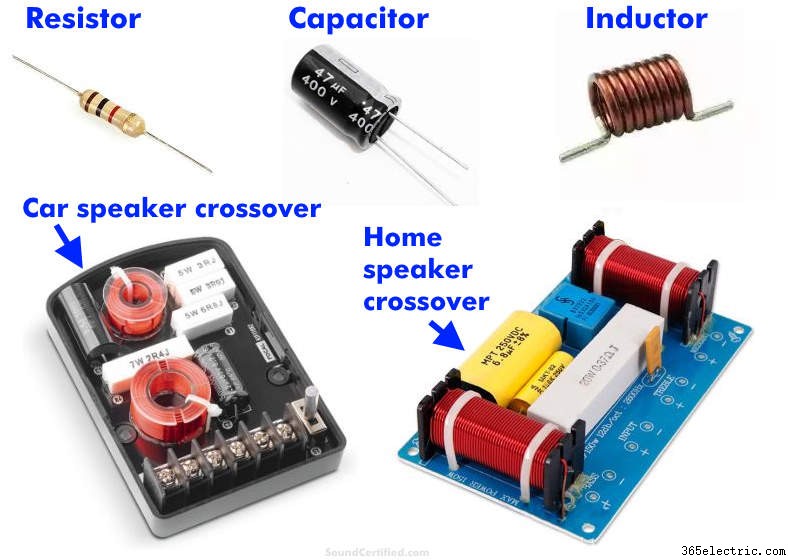
Les croisements de haut-parleurs (également appelés "passifs" car ils n'utilisent pas d'énergie électrique pour fonctionner) utilisent des condensateurs et des inductances qui sont sélectionnés en fonction des valeurs des pièces disponibles et de leur coût. Un crossover est conçu sur la base d'une fréquence Fc de départ et ajusté selon les besoins pour les objectifs de conception.
L'utilisation de la fréquence de croisement Fc comme point de départ permet aux concepteurs de systèmes de haut-parleurs de calculer les valeurs des pièces nécessaires (condensateurs et inductances) en fonction de l'impédance du haut-parleur. Étant donné que vous ne pouvez pas acheter de pièces à n'importe quelle valeur, le Fc que nous obtenons en fonction de ce que nous voulons est un bon point de départ avec lequel nous pouvons travailler et ajuster au besoin pour travailler avec des pièces en fonction de la disponibilité, du prix et d'autres facteurs.
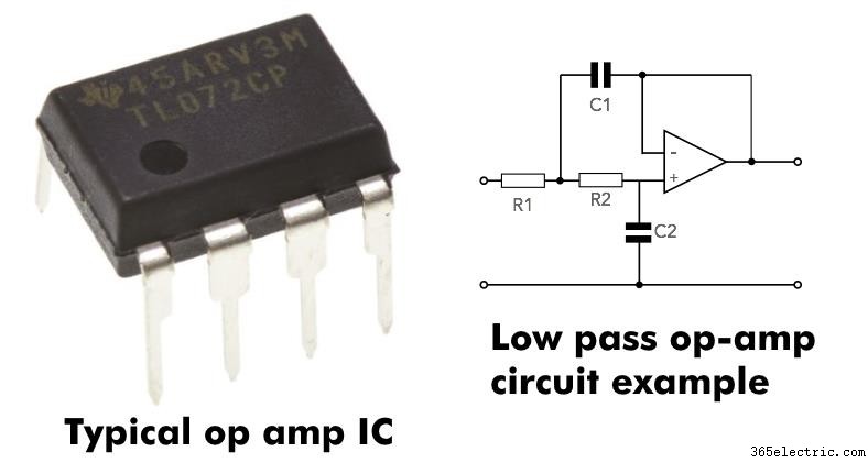
Les amplificateurs opérationnels, également appelés amplificateurs opérationnels, sont les éléments de base les plus importants pour les croisements électroniques. Electronic crossovers perform exactly the same job (and have the same basic behavior) as passive (speaker) crossovers. The difference is that they work on low-level signals before they’re amplified while passive crossovers work with amplified signals after the amp output.
NOTE: In this article while I describe how passive (non-electronic, non-powered) crossovers and Fc work, the principles are exactly the same for electronic filters.Just like their larger passive capacitor or inductor-based counterparts, operational amplifier based crossovers have the same slopes and crossover frequency behavior. They simply do it with the signal before it’s amplified instead of after it.
How to calculate decibels (dB) for the crossover frequency Fc
All sound frequencies after the crossover frequency are cut more and more past it with an increasingly steep reduction – to the point where they’re almost completely blocked.
In other words, a crossover filters out a range of sounds you’d like to prevent reaching speakers, starting at the crossover frequency.
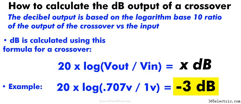
In the electrical engineering world, we traditionally use decibels (dB) when we talk about power measurements since they’re often non-linear. This just means that mathematically, power is often measured, charted, and tracked using exponential math such as logarithms (“10 to the power of x”, for example).
How crossover frequencies (Fc) and dB are related
Because crossovers reduce power at their output, it’s pretty common to measure the output reduction in decibels. One reason for this is that they have a gentle “slope” (downward curve) rather than a straight line if you were to see them graphed across the full range of audio frequencies.
For that and other reasons, we can measure the power output reduction in dB. To do so, you’ll need to know either (1) the power before and after the speaker/from the amp, or (2) the voltage at the speaker and from the amp.
Knowing those, you can easily calculate the dB output of a crossover with a scientific calculator on your computer or smartphone.
You can calculate dB for a crossover using these formulas:
- For voltage: 20 x log(Vout / Vin ) =x dB
- For power: 10 x log (Power_out / Power_in) =x dB
Understanding crossover signal level in vs out and “negative gain”
Crossover voltage out (called here “Vout”, the voltage to a speaker delivered from a crossover) can never be higher than the input – that’s not possible. Crossovers can only reduce the input directed to a speaker – they can’t amplify it. Some electronic crossovers do, but those intentionally have a gain on purpose and that’s not common in most cases.
For that reason, you’ll always get a negative dB answer if you do the math for the output of a crossover.
For the record, a negative dB value is used to show a reduction in engineering math while positive usually means a gain or increase in a signal. Amplifiers have a positive dB output (gain) while crossovers and some other components like resistors have a negative gain (a negative dB effect on a signal).
Attenuation is another way of describing a negative gain.
Remarque : the gain control of an amplifier is there to compensate for a high or low input signal level and is a separate section from the crossover circuitry.How a crossover frequency Fc works:example diagram
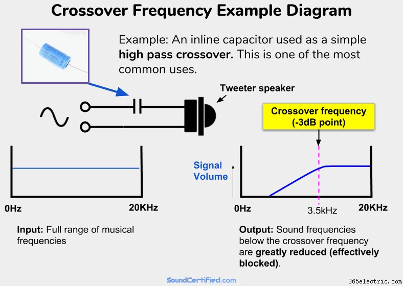
An example of a very common and simple high-pass crossover. A capacitor in series with a speaker will allow higher frequencies (above Fc) to pass with almost no volume or power drop to the speaker. It acts as a zero Ohm resistor (a short circuit wire) in series with it . However, for audio frequencies below Fc, the “resistance” (impedance, called capacitive reactance) of the capacitor will increase, allowing less and less voltage &power to reach the speaker. It will act like a very high-value resistor in series and therefore will block most of the signal from an amp sent to the speaker. In other words, a high-pass filter!
One of the problems I’ve found when we’re talking about this topic is picturing it in your mind. For example, it can be hard to understand what actually happens in real life when actually playing music in the real world vs just some explanation you’ve found on the internet.
All crossovers work the same – understand one, you understand them all (well, mostly!)
One important note I need to make is that the principles are the same regardless of the number of “orders”, or stages, a crossover has. For example, a simple 1st order crossover with a capacitor connected inline with a tweeter works on exactly the same principle as a fancier 2nd order 2-way crossover.
It’s just that the details are a little bit more complicated – not how Ça marche. That part never changes.
There are some crossovers with more sophisticated features &designs I won’t get into here, but for the most part, the majority are all the same and do the same thing to varying degrees. The great thing is that once you understand the basics very well, you’ve got it figured out for the most part!
The fundamentals of how crossovers work with Fc
The most important thing to know is that crossovers work by “absorbing”, or preventing, voltage and power from going to the speakers they’re connected to for the sound frequencies we don’t want them to play.
In the example from my diagram further above, you can see that:
- Above the cutoff frequency Fc, a capacitor acts like an almost zero resistance connection – nothing is blocked and it acts almost like a straight section of wire.
- When audio frequencies begin to reach Fc, the impedance of the crossover goes up, acting like a high-value resistor in series with the speaker. At Fc, the speaker receives only 1/2 the power it would otherwise (which also happens to be .707 times the input voltage from the amp or stereo).
- The farther we go past the Fc limit, the crossover’s impedance is much bigger in Ohms; in fact, past a certain point, it will be several hundred Ohms typically. When that happens the speaker has about 0v and no power to it.
As you can see elsewhere in my article, the “steepness” of the drop in the power &signal level to the speaker depends on the crossover slope. A crossover’s slope is basically just a result of how many “stages”, or crossover sections, are used as needed for the particular speaker system or speakers we’re working with.
Crossovers like you see here and are always in increments of 6 decibels (dB) Per Octave:
- 1st order crossover: a single capacitor or inductor is used, -6dB per octave reduction (not very steep).
- 2nd order crossover: Two components sections are used:one capacitor, one inductor. –12dB/octave reduction (steeper, more effective, very popular).
- 3rd order: two capacitors + 1 inductor or 2 inductors + 1 capacitor are used:–18dB/octave cutoff.
..and so on, with -12db being one of the most common crossover slopes you’ll find for both car audio crossovers and home audio speakers too.
An octave is just a half or double of an audio frequency. For example, 200Hz is an octave of 100Hz, 400Hz is one octave of 200Hz, then 800Hz, and so on. Equalizers and other audio electronics may use other variations with finer numbers like 1/3 octave, for example.Crossover frequency formula math:inductive and capacitive reactance explained
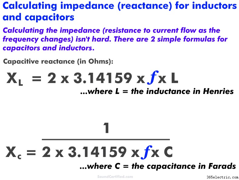
Shown here are the basic formulas for simple 1st order crossovers using capacitors and inductors. Capacitors have an impedance (Ohms) value that depends on the frequency just like inductors do.
Capacitors and inductors have a “resistance” called reactance (in Ohms just like resistance) that depends on the frequency. Here are a few basic things to understand:
- Capacitive reactance increases as the frequency DECREASES. It’s normally written as “Xc.” Capacitance is marked in units of Farads, with most capacitors being values in the microFarad (uF) range, nanoFarad (nF), or even picoFarad (pF).
- Inductive reactance INCREASES as the frequency increases. It’s normally written as “Xl.” Inductance is marked in units of Henries and typically found in units of microHenries (uH) or milliHenries (mH).
Again, it both cases, it’s just a form of impedance much like how a speaker voice coil that has a certain amount of inductance due to the coil of wire inside does. Both are measured in Ohms (Ω).
However, they complement each other and behave pretty much like the opposite of each other. For example:
- Capacitors act like high-pass filters when connected in series and low pass filters in parallel.
- Inductors act like low-pass filters when connected in series and high-pass-filters in parallel.
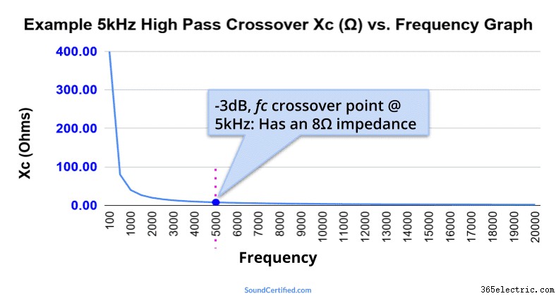
This graph shows an example of a simple high pass capacitor using a 3.98 microFarad capacitor with an 8Ω speaker with a crossover frequency (Fc) of 5kHz. At the Fc value, the impedance is the same as the speaker load (8Ω) which means the speaker power has dropped to 1/2. Further below Fc the impedance grows higher and higher, blocking bass frequencies more and more.
More great crossover and audio articles you’ll love
Don’t miss out on these fantastic articles just waiting for you to read &enjoy!
- Level up your audio knowledge in less than 10 minutes! Learn a ton of details about how crossovers work in this highly detailed article.
- What happens if you use a different speaker impedance with a crossover? It does make a difference, in fact!
- Want better sound from your car or home system? Find out what crossover frequencies to use here.
Need help? Don’t be shy! :)
Got comments, questions, or concerns? Friendly comments and requests for help are always accueillir! Just drop a comment below or reach out via my Contact page here.
Thanks!